
ELECTRONIC SYSTEMS DESIGN
RATIOTECH develops, designs and integrates embedded electronic systems using a global approach to meet the functional requirements, environmental constraints and standards specific to the customer’s application and sector of activity.
For us, “Design to Produce” means designing and developing your products with the following priorities:
- Architect to meet planning, manufacturing, operating and maintenance cost objectives
- Study, specify, document and justify proposed choices
- Modeling to verify compliance with functional, environmental and regulatory criteria
- Integrate certification and industrialization objectives right from the start architectural phases and at all stages of the R&D cycle
- Optimize system manufacturability, industrialization and maintainability
We work on projects in the following sectors :
- Aerospace and Medical
- Energy and Industry
- Automation and Production
Do you have an electronics development need?
METHODOLOGY
We apply an optimized development process to reduce the risk of iterations, which are costly, time-consuming and resource-intensive.
DISCOVER EVERY STEP OF OUR DEVELOPMENT PROCESS
We adapt it according to the technological maturity and planning objectives of each project.
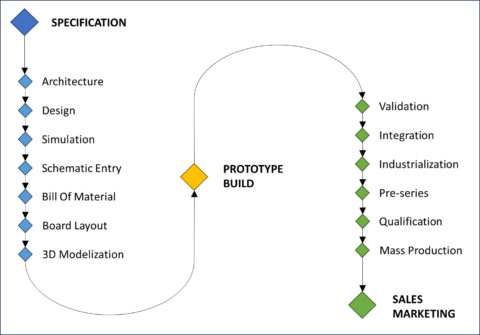
Development Process
This enables us to carry out development strictly in accordance with the V-cycle and with the rigor imposed by, for example, aeronautical, military or automotive standards.
When project constraints require it, we can also adopt a methodology inherited from the *Agile method* to offer greater flexibility and responsiveness, for example, to be able to derisit and realize a PoC (Proof of Concept) or rapidly prototype the introduction of new technologies.
TECHNOLOGIES
Our expertise in electronic systems enables us to develop technical and technological solutions that meet the needs of the aerospace, automotive, energy, telecommunications and industrial sectors.
DIGITAL
- 8-bit to 32-bit microcontroller-based computers
- Multi-core processors and 32-bit and 64-bit DSPs
- Digital signal processing
- SRAM, FRAM, DDR2 to DDR4 memories
- Interfaces USB3, PCIe Gen3/4, SDI, SGMII, RGMII, Ethernet
- Acquisition and generation of LF, HF, Audio and Video signals
ANALOG
- Conditioning of physical sensor signals
- Analog signal processing algorithms and implementations
- Low-noise and high-frequency signal processing
- High-efficiency, low-distortion amplification
- Lightning and ESD filtering and protection to industry standards
- 8-bit to 32-bit A/D and D/A conversion, low noise and high frequency
POWER
- BMS battery management systems
- DC and BLDC motor controller
- Switching high-power AC and DC networks
SUPPLY
- Reliable noise, high voltage, high current
- Linear power supply
- DC/DC conversion, Buck, Flyback, Boost, SEPIC, Buck-Boost
- AC/DC conversion, Single and Multiphase, Power factor correction
RADIO-FREQUENCY
- Near-field communication: RFID and NFC
- Remote interfaces : Bluetooth LE, Wifi, UWB, ZigBee
- 3G to 5G LTE modems
- Low-power networks: LoRaWan and SigFox
DEVELOPMENT PROCESS
In this section, discover our methodologies, know-how and expertise in the development of complex embedded boards and systems.
We present in detail the chronological steps involved in building successful projects, from expression of need to product launch.
SPECIFICATION
Identifying needs and expressing them, in other words, the specification, represents a key phase in your project. It’s important to formulate at least the functional expectations, the use cases, the constraints and the usage environment.
As a general rule, “the more carefully thought-out and detailed the expression of need, the greater the assurance of project execution control”.
We bring you our expertise to help you consolidate this decisive step.
ARCHITECTURE
Defining the architecture of the product, subsystem or electronic board is the most important technical phase of your project. It must respond precisely to the requirements of the specifications, and propose a relevant and appropriate solution to all the constraints of the project.
As every problem has several solutions, we advise you to carry out this phase iteratively, in order t o reach maturity.
Hardware Architecture Software Architecture
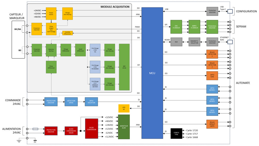
HARDWARE Architecture
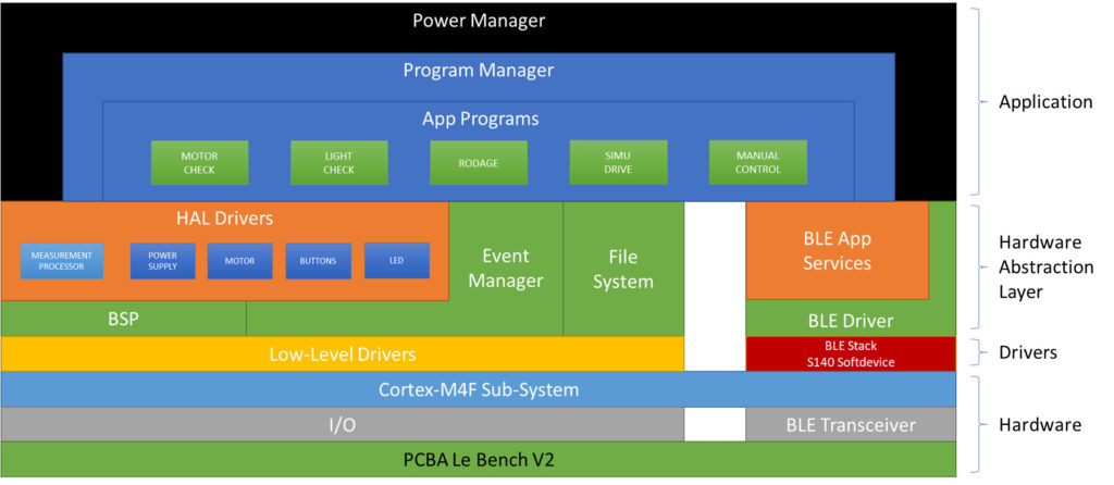
SOFTWARE Architecture
The architectural and technological choices are initially oriented by considering the objectives of planning, recurring costs and industrialization and operational maintenance.
Following the architectural study, the functional partitioning, the hardware and software technological solutions and the mechanical integration outline are defined to authorize business developments in a controlled context, ensuring a linear progress process and minimizing iteration risks.
Finally, the architectural study makes it possible to evaluate the recurring manufacturing costs of the board and the product, by providing a parts list of the main components identified.
DESIGN
We carry out both the design of electronic boards and the detailed implementation of the architecture to meet the requirements of the specification, both of which are defined upstream.
In this phase, we take into account functional, environmental, NRC and RC cost, production and industrialization requirements: EMC, signal integrity, thermal, operation at limits and robustness, cost optimization, maintainability and industrialization.
Technological choices as well as studies and computational justifications are documented to facilitate functional and environmental validation, after the manufacturing phase, to ensure that the resulting product conforms to design assumptions and specification requirements.
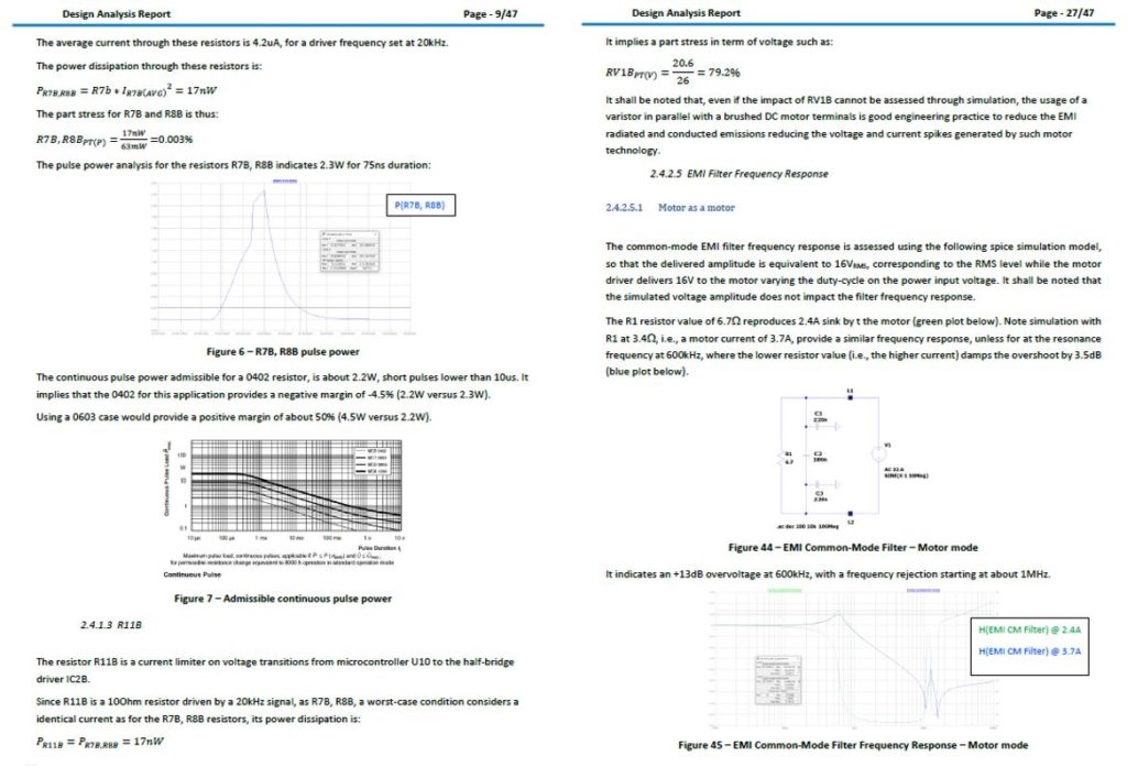
DESIGN SPECIFICATION
SIMULATION
Simulations allow us to verify design assumptions and calculations upstream of manufacturing.
The aim is to consolidate and de-risk the design in order to reduce the risk of iteration downstream of the development process. Our experience on simple to complex projects indicates that the risk of iteration on prototypes is reduced by around 50%.
Depending on the technical specifications of your project, we can carry out several types of simulations:
- Time and frequency simulation
- Signal integrity simulation before and after routing
- Power integrity simulation
- Multiphysics simulation: electromagnetic, thermal and fluidic
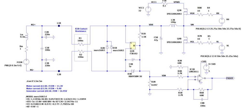
ModELISATION
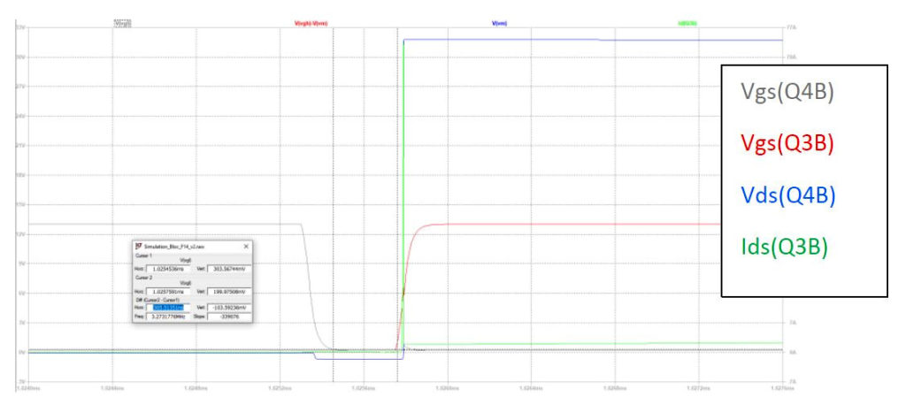
SIGNALS ANALYSIS
SCHEMATIC ENTRY
We create schematics based on the design study carried out upstream, which describes and justifies the choice of components and their interconnections.
To facilitate the review, analysis (evolutions, corrections, maintenance) and card placement and routing phases, we let’s create our diagrams using a hierarchical representation, an image of the map’s functional decomposition.
We create component libraries to provide understandable schematic representation, IPC-standard footprints to ensure product industrialization, and associated 3D representation to help validate component placement and enable integration of the 3D board model into the product’s mechanical design.
The set of interconnections (nets) is named and assigned to a specific class in order to define the constraints of physical track realization and layer assignment in terms of material, cross-section, width and spacing, meeting the requirements of current density and signal and power integrity.
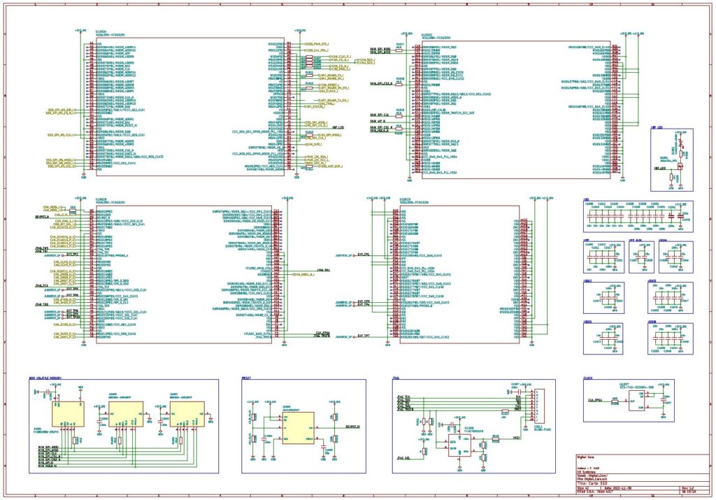
DIGITAL AND FPGA SECTION
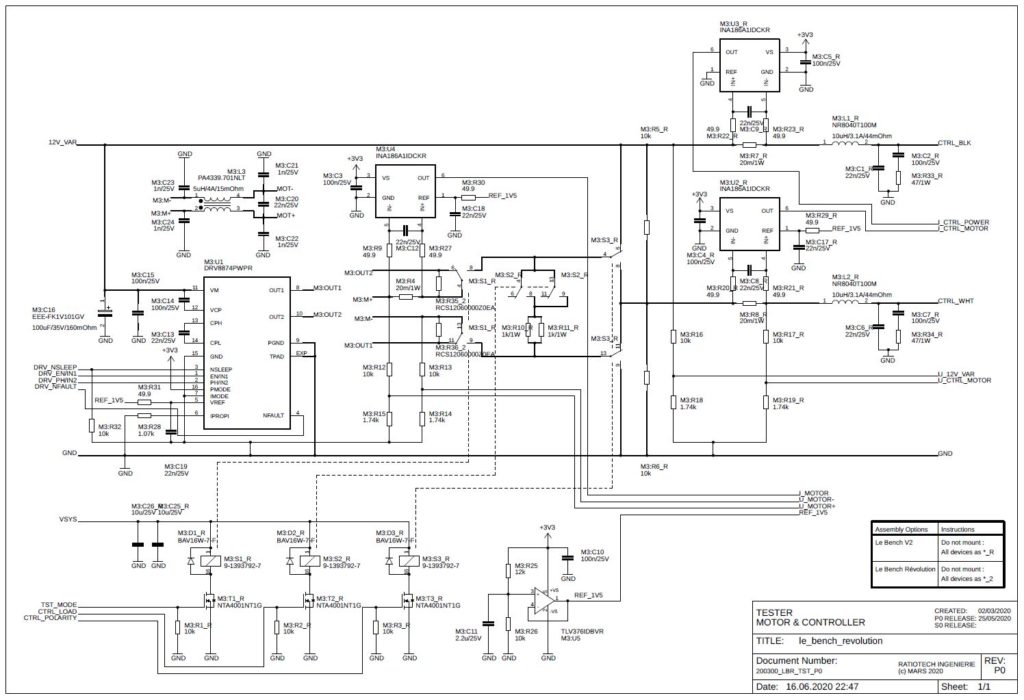
DC-MOTOR DRIVER
Our schematic entry process is thus carried out in the following chronological stages:
- Creation of component libraries integrating schematic representation, PCB footprint and 3D representation
- Creating a page hierarchy
- Positioning components and making interconnections
- Naming interconnections
- Assignment of interconnection classes in terms of current density
- Assigning interconnection classes i n terms of impedance and timing constraints
- Annotations in terms of placement and thermal and mechanical specifications
- Schematic review
BILL OF MATERIAL
The parts list is generated from the PCB schematic.
It allows us to consolidate the cost of series production of the electronic board, previously evaluated in the architecture phase, and to initiate the procurement of critical components.
We use a process developed to manage the risks of component supply and obsolescence as well as to ensure compliance with environmental and electrical safety standards for CE and FCC certification:
- Analysis of obsolescence risk and manufacturing status
- Adding second and third sources
- Compliance with REACH and RoHS standards
- Compliance with EN62368-1 and UL electrical safety standards Parts list
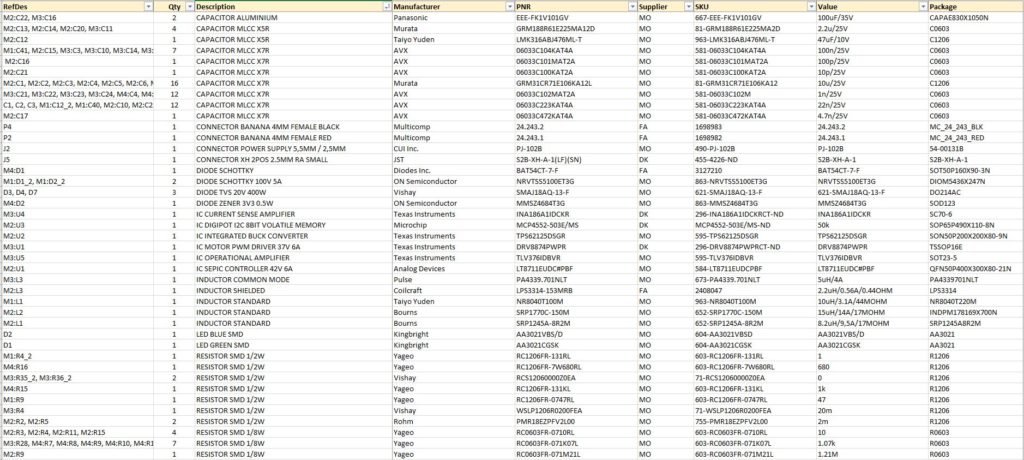
BILL OF MATERIAL
BOARD LAYOUT
Electronic board routing is a crucial technical phase, as it impacts manufacturing costs, functional performance, signal integrity, EMC, i.e. electro-magnetic compatibility (and therefore qualification/certification), thermal and vibration aspects, as well as the board’s manufacturability, testability and assembly/brazing.
We carry out the routing of electronic boards based on data from schematic input and a CAD specification written specifically for each board.
Our routing process is carried out in the following chronological stages:
- Study and definition of stack-up and vias typology
- Map contour import
- Definition of placement zones and mechanical and thermal stresses
- Definition and drawing of ground plans
- Positioning of mechanical holes and connectors
- Component placement by functional area
- Routing of power supplies, decouplings and filters
- Power signal routing
- Signal routing constrained in terms of signal integrity and timing
- Unconstrained signal routing
- Routing review
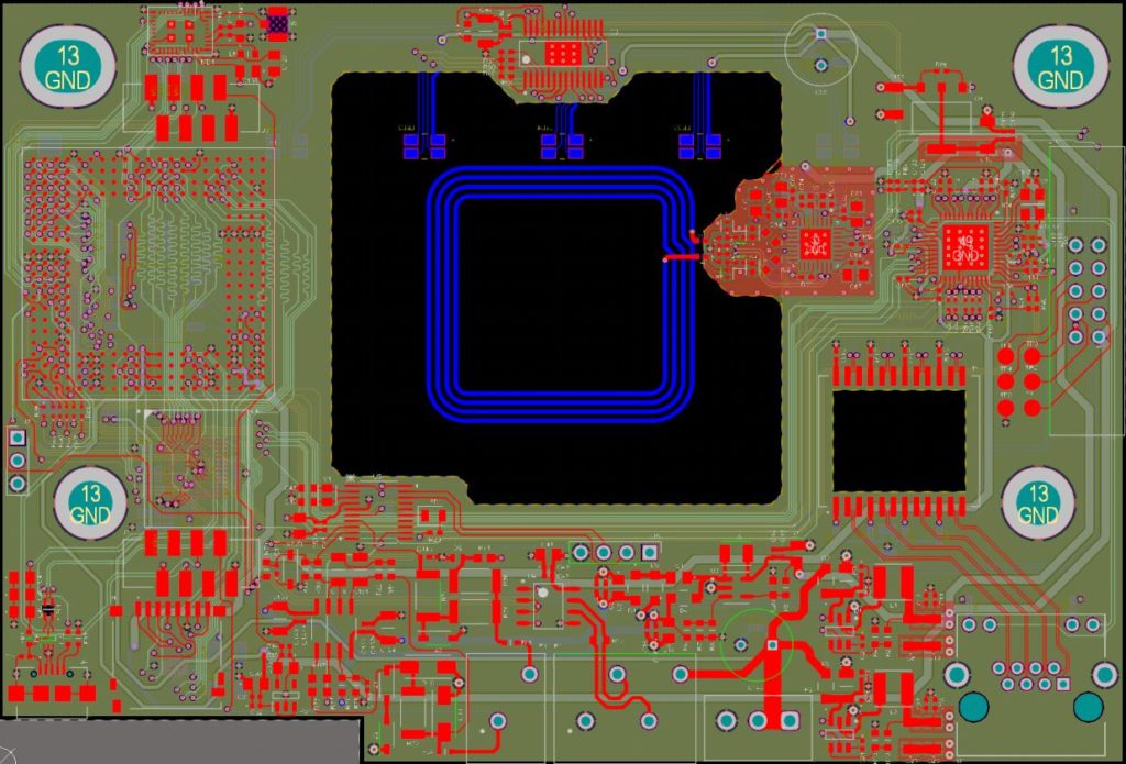
DIGITAL AND RF BOARD
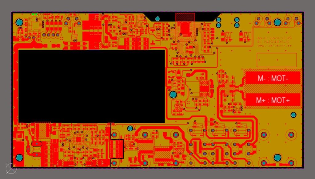
POWER AND RF BOARD
When creating component libraries, we make sure to associate a 3D model with the geometry of each component.
The 3D modeling of the board allows us to assess the positioning and accessibility of the components in terms of assembly and mounting. This modeling will then be used to obtain a complete 3D model of the product mechanics integrating the electronic board.
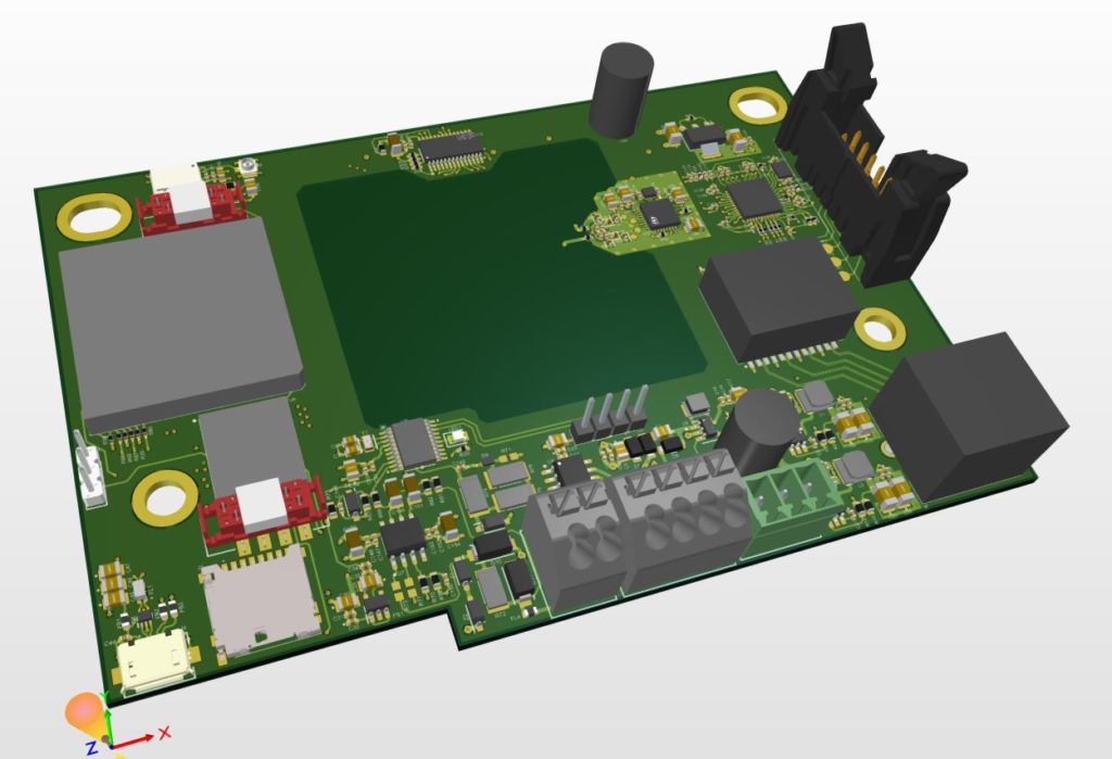
DIGITAL AND RF BOARD
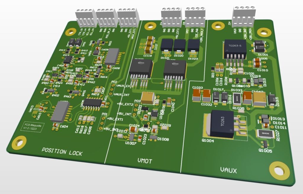
BRING-UP BOARD
3D MODELIZATION AND MULTI-PHYSICS SIMULATION
We integrate the 3D model of the electronic board into the 3D mechanical model of the housing or host mechanical assembly, before initiating board and mechanical manufacturing, in order to check and correct the following aspects if necessary:
- Interfaces for fixing and holding the electronic board
- The risk of collision between the board, its components and the mechanical components of the case
- Position and accessibility of connectors, buttons and displays for installation and use cases
- Cable routing and length margins for internal wiring
- Validate and optimize assembly range in preparation for production
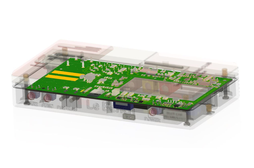
DC-MOTOR TEST BENCH
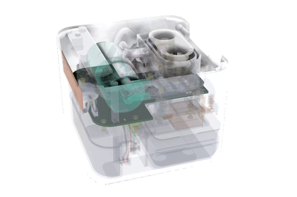
AUDIO HEADSET CLEANING
Combined modelisation of electronic boards with mechanics also enables us to carry out multi-physics simulations to check design conformity with architectural and design requirements, and reduce the risk of iterations occurring.
- Static and flow thermal simulation
- Vibration simulation, mode and stress analysis
- EMC and RF simulation, inter-cable crosstalk analysis and RF performance evaluation
MANUFACTURING
We entrust the manufacturing of PCBs and the wiring of boards to our specialized EMS partners, as required, for rapid prototyping or mass production.
We provide configuration management for definition files, supply management, manufacturing monitoring and quality control procedures.
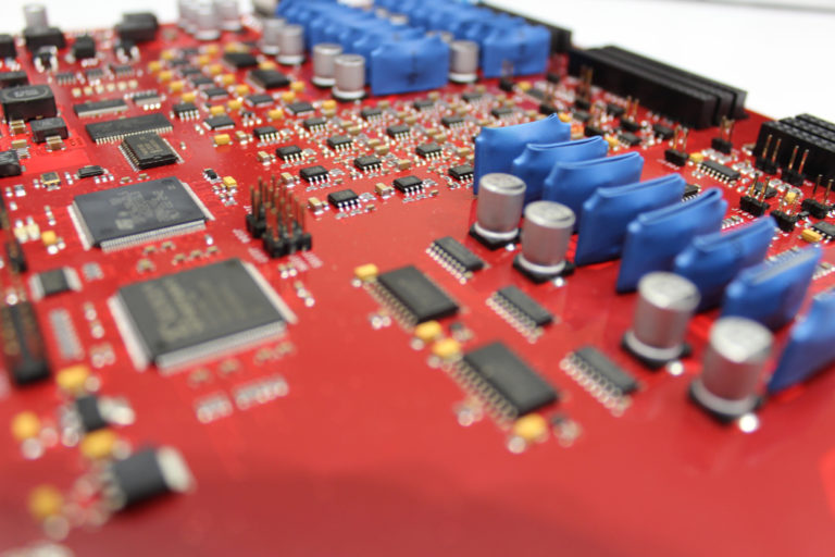
Prototype BOARD
We have an additive printing production unit comprising 5 3D printers, enabling us to produce prototypes and pre-production runs in short timescales, and offering the flexibility needed to make mechanical adjustments during the fine-tuning phase.
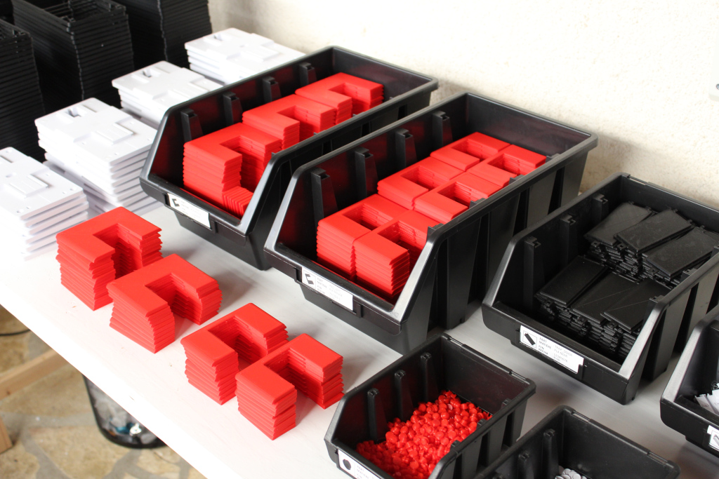
MANUFACTURING SERIES OF PARTS
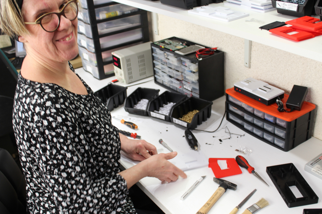
Mechanical assembly shop
Our know-how and experience in additive printing production enable us to produce parts in polymers such as PLA, ABS or PETG with quality control and high production repeatability, for both static and kinematic assemblies.
VALIDATION
Our electrical measurement laboratory enables us to carry out the following tasks: validation, fine-tuning, analysis and EMC pre-certification of electronic boards for:
- Precision and high-frequency analog
- Complex, high-speed processing and digital transmission over parallel, serial and differential buses
- Power supply and power converter
- Radio-frequency transmission
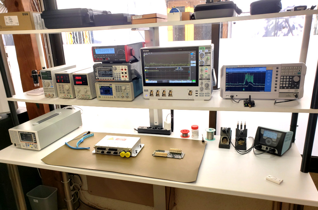
Test and measurement laboratory
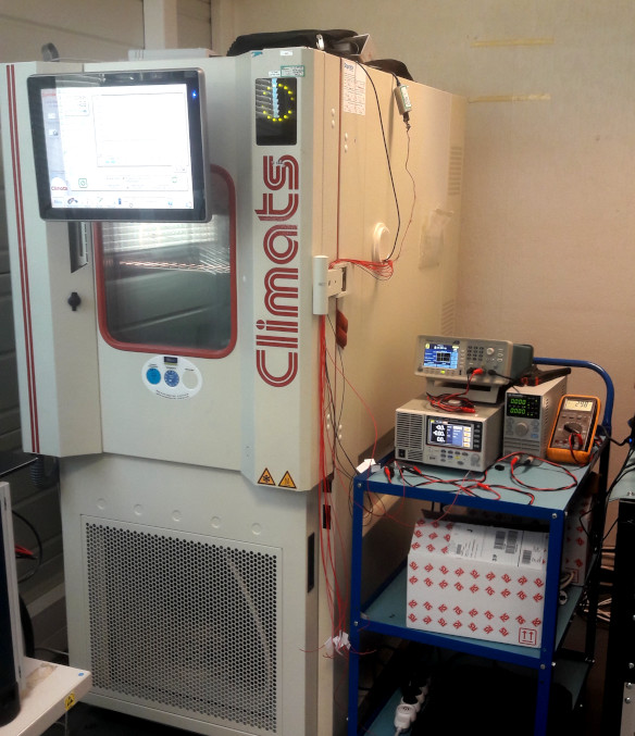
Climatic chamber tests
As required, we carry out climatic tests to determine validate the robustness and functional compliance of products developed over their operational temperature range, with the ability to cover a range from -50°C to +125°C.
SOFTWARE AND MECHANICAL INTEGRATION
Our design office has the skills to carry out the development of embedded software on microcontrollers, processors and FPGAs. We develop in bare-metal environment as well as under Real-Time OS such as freeRTOS.
We develop the appropriate tools (hardware probes and software scripts) to facilitate the setup and programming of the targets to be programmed in their mechanical environment.
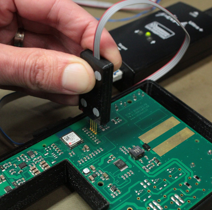
Embedded software programming
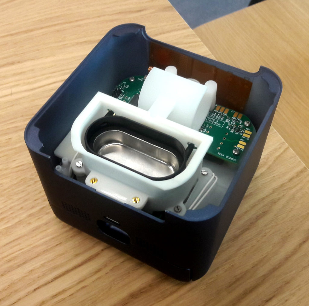
Mechanical integration
The mechanical integration phase enables us to validate :
- Static and kinematic interactions of mechanics with electronic circuits and wiring harnesses
- Assembly range, component accessibility and maintainability
- Electro-magnetic, thermal and fluidic interactions
- Wear resistance, vibration resistance and shock resistance
- Ergonomics of use cases and user interface
INDUSTRIALIZATION
The documents written and generated at each stage of the development process are grouped together in a package to obtain the design, procurement and manufacturing files.
We model the product assembly range using virtual 3D scenarios. This enables us to identify, upstream of production investments,
optimizations in terms of execution time, specific tooling requirements and costs.
The essential characteristics of each manufactured element are identified and quantified in order to determine acceptability criteria based on the expected output in series production.
ASSEMBLY STEPS MODELING
QUALIFICATION
We can help you draw up qualification and certification plans, and prepare the associated technical documentation.
Together with accredited measurement laboratories, we organize the
EMC, EMF, Radio Frequency, Electrical Safety, Vibration, Temperature and Humidity test planning. We can also set up, control and optimize measurement setups in collaboration with laboratories.
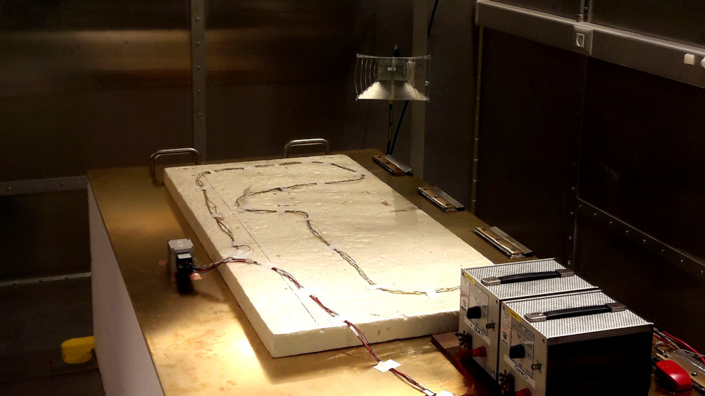
MEASUREMENT OF RADIATED EMISSIONS
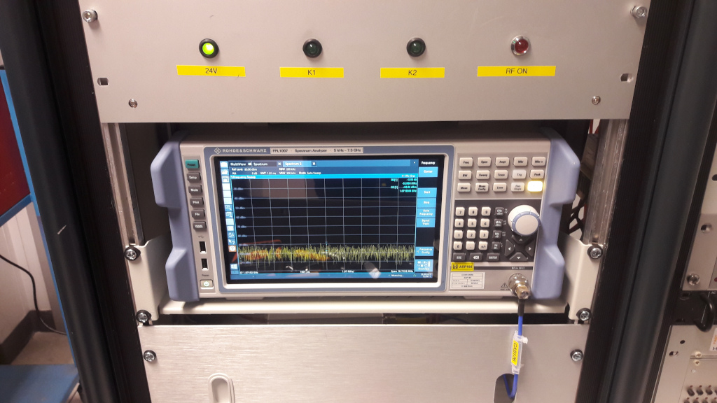
SPECTRAL ANALYSIS
We also carry out EMC pre-certification campaigns (upstream phase) and investigations (downstream phase) in our own laboratory and in an anechoic chamber a t a partner laboratory.
Do you have an electronics development need?
SOFTWARE TOOLS
Our expertise in CAD tools enables us to use a wide range of CAD solutions on the market, depending on the needs of the projects we are entrusted with.
Electrical Simulation and Signal Integrity
- LTSpice, QUCS, Tina
- PCB Toolkit
- Hyperlynx
- Altium Designer
Schematic Entry and Board Layout
- Altium Designer, Cadence, Mentor et Cadstar
- KiCad et Eagle
Mechanical Modelization
- Autodesk Fusion 360
- PCB-Investigator Physics
(*) Licenses acquired according to project needs
